

Corel CAD is advertised as a 32-bit design tool for easy, accurate and realistic modelling of real world objects in three dimensions. Corel CAD boasts a fully customisable Corel DRAW/Windows 95/NT interface incorporating the Industry standard ACIS (Spatial Technologies Corp) solid modelling engine, giving it the flexibility to conceptualise, construct and revise product models and prototypes on a PC.
Corel CAD (3D) incorporates Boolean operations (union, subtraction and intersection), surface blending and trimming, and 2D profile extrusion capabilities, in addition to normal 2D CAD drafting features. The Corel CAD package also boasts exceptional rendering capabilities to view 3D models with realistic shading and textures. The package includes a comprehensive collection of 2D drafting symbols, 3D models (DXF Format and Corel DREAM Format) as well as a number of utilities to enhance the design process.
Corel CAD differs significantly from Corel Visual CADD, reviewed in the November issue of SIXTEEN BITS. Corel CAD has full 3D solid modelling and rendering capabilities, while Corel Visual CADD is a two-dimensional drafting package for 2D presentation drawings.
The Corel CAD Software Bundle
The complete Corel CAD software bundle comes on 2 CD-ROMS and includes:
 Corel CAD
Corel DREAM 3D
Corel MULTIMEDIA MANGER 6
Corel Print Space
Corel SCRIPT
Corel MEMO
200 Corel House Select sample house plans
120 Corel True Type Fonts
Corel Vector, Raster, Image and Animation Filters
7000 2D Drafting Symbols
600 3D Symbols in DXF Format
750 Corel DREAM 3D Models in Corel proprietary format
750 Full Colour Bitmap Textures in Bitmap format
200 Photo Background images in CDR Format and100 sample drawings.
All up, there are over 1000 Mb of software, models and images available on the 2 CD-ROMs. For this review I needed to significantly increase my hard drive capacity. I had been seriously considering buying a new 2Gb hard drive for video work and to complement my existing 1.2Gb drive: this review made my decision to purchase a new drive much easier. One of the drawbacks of detailed 3D modelling and animation are the large file sizes generated by 3D models and rendered images.
Software Installation
Installation was from the CD-ROMs, using the standard Windows 95 Add/Delete Programs option from the Windows 95 Control Panel. Installation was straightforward and included the options of Typical, Compact or Custom installation. The Typical installation requires 48 Mb of disk space and installs Corel CAD, Corel DREAM 3D, Corel MULTIMEDIA MANAGER, Corel MEMO, and additional fonts.
The Compact installation requires about 40 Mb of disk space and loads only those files required to run Corel CAD. The Custom installation requires up to 107 Mb of disk space depending on the options chosen. This option allows you to install Corel CAD, Corel DREAM 3D, Corel MULTIMEDIA MANAGER, Corel MEMO, Corel Print Space, Corel SCRIPT, additional fonts, sample design files, and import/export filters.
I chose the Custom installation option and selected Corel CAD, Corel Print Space, Corel SCRIPT, various additional True Type Fonts, and the full range of import/export filters, in particular the Autodesk DXF and DWG drawing translation option. I was disappointed that there was no International Graphics Exchange Specification (IGES) option, which is now the International standard for 3D Model data exchange format.
I chose to load only a limited number of 2D and 3D symbol objects from the comprehensive range of symbol libraries. I did not load any of the house plans, sample drawings, texture images or background images. Any drawings or images that I required could be loaded directly off the CD-ROM rather than take up valuable hard drive space.
The actual installation took only a few minutes and was relatively trouble free. A minor problem occurred when I typed in the serial number supplied with the CD-ROM and I kept on getting an error message advising me that the serial number of the product was incorrect. After several attempts at retyping the serial number I chose the ignore the error message option, and the installation was completed. It was interesting to note that Corel CAD software recognised the serial number and displayed the number along with my registration details. However, Corel Print Space flatly refused to recognise that I was a registered user.
Windows 95 Interface
The user interface has a standard windows software look and feel, with the standard Windows Menu Bar, Speed Bar Icons and Status Bar. The user interface also includes additional toolbars that can remain 'floating' or can be embedded on either the right hand or left hand side of the screen. The toolbars provide quick and easy access to all drawing/modelling tools and to some of the more important drawing/modelling and editing commands.
All drawing/modelling commands could be accessed in a number of ways by using either the menu bar pulldown options, the icon toolbar/toolboxes and pullout options, or by keyboard short cuts. Corel CAD follows the standard Windows format in that all commands are available from the standard Menu Bar as well as from flyout icons and keyboard short cuts. This makes the software relatively easy to use and learn for first time users familiar with the Windows 95 operating environment.
Toolbars/Tool Boxes
Toolbars and toolboxes are excellent. Toolbars can remain floating or they can be docked into to any part of the screen environment. Also Toolbars can be customised to include any command you want in that toolbar, or you could make you own Toolbar. Toolbars consist of Toolboxes or Icons which initiate the command. My main gripe with the toolbox icon is that the drop down caption explaining the icon function only appears for the current selected icon. For a Toolbox that has several options, you have to make the icon active from the toolbox flyout before the caption explaining the icon function appears.
Pop Up or Roll Up Dialogue Boxes
Corel CAD uses a number of 'Roll Up' dialogue boxes in order to input commands and coordinates. I must admit I found these roll up menus strange at first until I got used to them. For example, during insertion of Cartesian and Polar coordinates, the move command, primitive object insertion and object material properties are all controlled by roll up dialogue menus. Most roll up menus remain active and can be simply rolled up and put to one side whilst other 'pop up' menus are only activated when you actually select the appropriate command.
Right Mouse Button - Context-Sensitive Pop Up Menus
Right mouse button options are limited. There are no context-sensitive help options using the right mouse button. Options are limited to changing the properties of the various tool bars or saving your model file, and cutting and pasting objects.
 Keyboard Shortcuts
Key board shortcuts are few, cryptic and convoluted. For example, the keyboard shortcut for moving an object is to type V at the command prompt. I would have thought M would be more apt. The screen refresh and zoom fit shortcuts are Control + Shift +Q and Control + Shift + W respectively-your fingers sure get a work out! There appear to be no keyboard shortcuts for basic drawing and modelling functions, eg draw a line, circle or arc, etc. I must admit that I tended to use only pulldown menus and toolbars/toolboxes to initiate commands.
User Manual
The User Manual accompanying Corel CAD is relatively light on, given the complexity and power of the product stated in the advertising blurb and also given the price of the software. The manual is organised in a number of sections:
Introduction
Corel CAD Tutorials
Corel DREAM 3D Tutorials
Corel MULTIMEDIA MANAGER
Corel SCRIPT, comprehensive descriptions of the 2D/3D symbol libraries
3D DXF models
3D Corel DREAM 3D models, and texture bitmaps.
The introduction covers software installation and technical support whilst the remainder of the manual is devoted to the tutorials and symbol libraries. The tutorial section uses 13 self paced tutorial based lessons designed to guide you through the workings of screen work area, menu command structure, through to creating and rendering a 3D model.
The core of the Corel CAD manual is given over to cataloguing the comprehensive 2D and 3D symbol libraries (which I chose not to install). There are also brief sections on Corel DREAM 3D, Corel MULTIMEDIA MANAGER and Corel SCRIPT. The Corel DREAM 3D section of the manual is also based on a tutorial style description of the software rather than a reference manual. Nowhere in the User Manual is there a section on individual commands, or detailed descriptions of the command structure or various command options. The manual index is also very basic and, because of the tutorial based material, it is difficult, if not impossible, to use the manual index to quickly find a specific command or reference.
I must admit I was disappointed when I opened the package and thought that there was a manual missing, as the User Manual was more akin to a user tutorial and description of the package contents, than a comprehensive software user and reference manual.
Overall, I found the Corel CAD hardcopy User Manual disappointing and lacking in depth. There was no reference at all to Print Space. Some commands were not listed, an example being the spiral sweep command. Other commands omitted or not adequately covered were primitive object creation, materials editing, perspective viewing and rendering, to name but a few.
The Corel CAD manual is a reasonable tutorial and guide for first time users but does not adequately or accurately describe the software. In fact, I believe the existing manual does Corel CAD a major injustice in that it does not truly represent the software or adequately describe the power and function of the CAD application.
Online Help
The online help was much more informative. All command information is easily accessed and the Search options and related topics options are intuitive and easy to use. Hypertext and related topics links are relevant and can be used to gain access to detailed command structure, options and other information, although the online information tends to be brief. For this review I relied almost entirely on the online help to get information.
A minor problem I found was inconsistent terminology. For example, when creating a complex shape to extrude into a solid state, I received an error message stating that the profile needed to be defined as a region. A search of the online help did not list 'region'. After searching various topics I found a minor reference to regions under the Define an Object listing in the online help.
Initial Impressions
Having previously reviewed Corel Visual CADD, 2D drafting software, I found the Corel CAD (3D) Windows 95 user interface familiar and both the 2D and 3D icon pullout toolbars and tool boxes relatively easy to interpret and use. I got to know and 'love' using roll up menus and finished up using them to good effect.
Initially I had problems with the 3D command structure and syntax. I found the way Corel CAD treated Cartesian and Polar co-ordinate entry and Boolean operations annoying and cumbersome, but then I got used to the method and I accepted the system. I suppose this was a legacy of using several different CAD systems: you become fixed in the way you approach and do things based on the way a particular software application functions and you hate learning a new system.
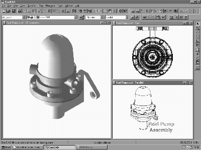
I briefly looked at the tutorial exercises and decided to launch into something more complex in order to force me to use the majority of the software's functionality rather than doodle with tutorials. The tutorials in the manual looked very ordinary and did not pose a challenge to any serious 3D modeller. I chose to model a simple fuel pump assembly which could be modelled from basic primitive and swept profiles. The fuel pump model also required the construction of internal galleries and drilled holes, which would give the software a reasonable workout. All up, the Fuel Pump took me approximately 4-5 hours to complete. Bear in mind that I was well down the learning curve in regard to using the Corel CAD software. I knew how to build the model, but knew nothing about the Corel CAD software, although I am conversant with solid modelling techniques.
3D Modelling/2D Drawing
Options/Preferences
The initial modelling environment setup is accomplished using the Tools/Options dialogue box. The Tools/Options are intuitive and self explanatory, but do not provide the user with a great deal of flexibility in regard to screen preferences. Units (metric or imperial), angular precision, grid settings, etc were all relatively easy to find and set. Had I been smarter, I could have gone straight to the template directory and opened up a new drawing based on an excellent range of preset engineering, architectural and general drawing templates. Other options include dimension styles, text styles, font selection, etc. All were also easy to find and set to my chosen modelling environment.
Layer Management
Setting up of the drawing layers was also easily accomplished using the Tools/Layer Manager dialogue box selected from either the Menu Bar or Standard Toolbar. Controlling and setting layer attributes such as layer visibility, colour and line type, printability and line weight, is achieved by simply editing the appropriate layer and setting the new values from a series of predefined options. Corel CAD also allows you to define and group layers. For example, you could define the layers diaphragm, upper diaphragm, lower diaphragm, diaphragm bolt, etc into a group named Diaphragm Assembly. Grouping layers allows more effective control over the display and printing of your 3D model.
 Coordinate System
Corel CAD uses the conventional 3D Cartesian coordinate system. Coordinate values can be entered as either absolute values with respect to the origin (0,0,0), relative values with respect to the previous point, or as an offset value with respect to a user-selected point. The offset method of co-ordinate entry is extremely practical: once you understand the concept you can use the command to great effect. Some higher end CAD systems have a similar system using co-ordinate filters, but the Corel CAD system is superior.
Corel CAD uses the conventional Polar (2D) and Spherical (3D) coordinate system. Polar co-ordinates are specified in terms of line length and angle in the XY plane (azimuth) whereas spherical coordinates are specified in terms of line length and angles in the XY (azimuth) and XZ planes (elevation). Polar and spherical co-ordinate angles can be specified in either a mathematical format (where the X axis represents zero degrees) or in a geographical format (where the Y axis represents zero degrees or North).
Personally I found that one of the most annoying features of Corel CAD was the way in which Cartesian or Polar coordinate values are actually entered. To draw a straight line between two points, you first select the line command, press the insert key to bring up the insert roll up dialogue box, choose the Cartesian or Polar coordinate tab option, toggle to the X Axis box and type in the X axis co-ordinate value (or alternatively use the near-useless incremental buttons), do the same for the Y axis and the same again for the Z axis coordinate values, select the Relative, Absolute or Offset option, then press the apply button to actually apply the coordinates. Then to terminate the command you must press control + enter to terminate the insert command and roll up the roll up menu, then press enter to terminate the line command, and then press the Esc key at least twice in order to get back to the command prompt. Whew! Now that is what I call a productivity enhancement!
3D Cursor
Corel CAD uses a tricoloured 3D cursor to indicate the principal 3D axes. The axes displayed depend on the particular active view. In any axonometric view (3D views) the colour is black for the X axis, red for the Y axis and green for the Z axis. In the Front View only the X and Z axes are displayed, and in the Top View only the X and Y axes are displayed. There is no indication of the location of the system origin (the 0,0,0 point). An icon representing the absolute Origin of any CAD system is a must, particularly when learning 3D. As a teacher of 3D CAD I am only too aware of the difficulties students have when navigating 3D space. A homing beacon or icon clearly showing the direction of the principle axes and origin of the 3D universe is absolutely essential.
Corel CAD does not use the concept of user definable Construction Planes or Working Planes. All models and primitives must be created with respect to a fixed construction plane where the X axis governs the length, the Y axis governs the width and the Z axis governs the height. Models or primitives must then be rotated and moved into their respective positions. Most 3D CAD systems incorporate a system of a user definable construction plane where a local construction plane or user co-ordinate system can be manipulated into any position, and the model created with respect to that local working or construction plane. This system of user definable construction planes makes 3D modelling extremely flexible and easy and the productivity gains can be very high.
 Viewing 3D Models
Corel CAD comes with a comprehensive range of preset views for both orthogonal viewing (plan, elevation, side elevations, etc) and axonometric viewing (South-East isometric, North-West isometric, etc). Changing the view angle is as simple as clicking an icon or selecting a named view from a pulldown list. There is also a dynamic viewing angle icon which allows you to dynamically change your viewing perspective to a dimetric or trimetric axonometric viewpoint. Any user defined viewpoints can be saved as a Named View for later use. I found all the viewing options intuitive and extremely easy to use.
For those not familiar with things 3D, an axonometric view is any 3D view defined by a set of direction vectors with respect to the X, Y and Z axes. An isometric view is a view where the direction vectors defining the viewing angle are all equal about all three axes. A dimetric view is where any two of the direction vectors are equal and a trimetric view is where all three direction vectors are unequal.
Working with Multiple Viewports/Windows
There are at least a dozen preset multiple viewports available from the layout options. If you can't get by with any of those, you can configure your screen using standard windows viewport sizing techniques and save your preferred screen configuration as a preset. Working with multiple viewports and windows is simple and effective. Windows or viewports are made active by clicking any portion of the working window. When working in 3D (on a flat 2D screen) it is absolutely essential that you are able to view at least three different perspectives of your model to gauge topological accuracy.
2D Drafting Capabilities
Corel CAD's 2D drafting capabilities are adequate for a 3D modeller. I note the advertising material promotes equal 2D and 3D drawing capability. Corel CAD is definitely a dedicated 3D system with some 2D capability. Text and dimensioning are adequate, but not brilliant. All the standard 2D editing commands such as trim, offset, extend, etc. are available, but the real power of Corel CAD is in the 2D (wireframe and surface/region) and 3D Object Creation tools. Text and dimension placement in the 3D mode is awkward and tricky, although the dimensioning is intelligent when placing dimensions in 3D. I found the 2D dimensioning quite different to dimensioning in conventional CAD packages.
Object Snaps
Corel CAD has an excellent system of setting running object snap points, with an intelligent cursor that highlights the snap point. Also, the current settings for object snaps can be temporarily overridden by turning off the settings for a one-off object snap selection. For example, you can have the end point, mid point and intersection permanently selected, then turn off the running object snap, snap to the centre of a circle, turn the running object snaps on again and resume.
Object Selection (Windowing)
Corel CAD does not appear to have a multiple entity selection ability. Each entity must be selected individually; however, cumulative entity selection can be achieved by holding down the shift key and selecting objects. There appear to be no windowing selection methods either by total window enclosure or by a window 'crossing box'.
Creating/Modifying 3D Objects
Solid Models are objects are created from either the Boolean addition (union), subtraction or intersection of primitive building blocks such as cubes, wedges, cylinders, cones, etc or from extruding or sweeping complex predefined closed regions. You need to be able to break down complex bodies or 3D shapes into their most fundamental building blocks in order to model the object. To create a flat plate with a hole (or several holes) you can build the plate from a primitive block, then place a cylinder or number of cylinders representing the holes and simply subtract the
cylinders from the plate, and voil�: a plate with hole/s! Alternatively, you can create a square region, place the circles representing the holes, subtract the holes from the square, and then extrude the resulting shape to give it thickness and you have the same plate with hole/s.
The simple creation of both 2D and 3D primitive objects is perhaps Corel CAD's strongest feature. The Object Insert roll up dialogue box presents you with a range of options. In fact, after I got to know and love this option I very rarely resorted to using the 2D drawing functions (lines, arcs and circles). For working in 3D I tended to create all objects as surfaces (regions) and then used the Boolean operations to create the complex profiles for extrusion or sweeping. Again, the Corel terminology issue is raised. In fact the shapes that Corel names surfaces are regions. This is backed up by the error messages you get when you try to subtract or add one region (surface) from another. The error message states that the objects must be either a solid or a region.
When using the Object creation dialogue box you can create (both wireframe and surfaces/regions) all manner of complex 2D closed shapes such as polygons, circles, ellipses, and donuts (the 2D equivalent of a toroid). You can then use the Boolean operations to create a complex profile for either extrusion or for sweeping about an axis. The same Object dialogue box also allows you to give the predefined shape depth, eg giving a square depth in order to make a cube. The Object creation dialogue box has numerous options for the creation of cubes, blocks wedges, cylinders, elliptical cylinders, pyramids, cones, spheres, tori, etc.
Boolean Operations
The standard Boolean operations are addition or union, subtraction or intersection. Corel CAD highlights each selected entity in a green bounding box which greatly aids the selection of individual items from a complex assembly. Corel CAD does not appear to allow you to select more than one item for subtraction. To create the 6 holes in the body of the Fuel Pump, I had to create the 6 cylinders representing the holes and then subtract each one individually from the main body. I should have been able to select multiple items to be subtracted. Apart from the inability to subtract multiple objects for subtraction, the operation of the Boolean functions is extremely good and the software was extremely stable during some very complex Boolean operations.
The Spiral Sweep Command
Corel CAD incorporates a unique spiral sweep command as part of the extrude options. A helix is one of the hardest entities to create in a solid modeller but the spiral sweep command does it easily. I used the spiral option to create the diaphragm return spring. Many years ago, I wrote a macro for a solid modeller to create machine threads. As I recall, it was no easy task and my macro was far from perfect. The spiral sweep command is not mentioned in the User Manual and I had to rely on the online help and experimentation to get the result I required.
Modifying 3D Assemblies
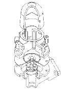
Generally modifying a 3D Solid Model is restricted to a few basic operations such as chamfering and filleting edges or stretching a model to change the physical size, but not the basic topology, of the model. All of Corel CAD's modification commands are very easy to use: on selection of the fillet or chamfer command, a roll up menu appears, prompting you for the radius of the fillet or distance of the chamfer. Models can also be sliced in two using the 3D Slice and 3D Trim commands. To create the cut away sections of the Fuel Pump, I sliced each individual component into four quarters (like slicing an orange into quarters), deleted the quarter that was not required, and then 'unioned' or added the remaining three quarter sections into one body again. The slice command normally allows you to retain both parts of the model whilst the 3D trim command allows you to specify the part of the model you wish to keep. In the case of the main body of the pump: every time I sliced the model one half would be automatically deleted. To work around the problem, I created a large cube and then subtracted the cube from the body to achieve the same effect.
Visualising 3D Models
Model refinement in terms of surface and line resolution can be quickly and effectively controlled using a slide bar. Low refinement produce very quick refresh rates especially when the model database is large. Changing the refinement level for more realistic rendering and hidden line removal is a simple matter of increasing the slide bars to the desired level. Working with the model at the maximum surface and line refinement level eats up the processing power of your computer and slowed my machine down to crawl.
 Visual display of 3D models is probably Corel CAD's strongest attribute. Corel's shading and rendering routines are simply the best I have ever seen or used. All the inbuilt rendering routines for flat, Phong and Gouraud shading are extremely quick and produce very realistic shaded images. The raytracing preview and full raytracing routines are fully functional, easy to set up and use, and exceptionally fast. The images produced for this review were literally created in seconds at medium to high model refinement, using the full preview option with no shadow casting. I created a fully raytraced image in a matter of minutes. Admittedly, it was at a medium refinement; however, the image was so 'photographic' that it was not suitable as an engineering representation. There was too much shadow and reflection off the polished aluminium surfaces of the pump body. Even in the glass bowl, all the models below were reflected off the bowl's glass surface. From a computer generated graphics viewpoint, the image was superb; however, as an engineering visualisation exercise, the image was over the top.
A general comment: I have used several very expensive addon utilities to CAD programs specifically designed for model visualisation and rendering, and they are not a patch on Corel CAD's inbuilt render. I could not understand why Corel recommended that models be imported into Corel DREAM 3D for further rendering.
Now the downside. The hidden line removal routine is possibly one of the worst I have encountered. Hidden line removal, even at very low model refinement levels, is unbelievably slow. It was my experience that when the model database was large the routine simply could not cope and literally gave up. I tried several times, without success, to produce a hidden line image of the exploded cutaway view of the Fuel Pump, at a medium to high refinement level. The hidden line algorithm appeared not to be able to cope with the complexity of the model. On the other hand, I could produce a rendered image on the screen at the same model refinement level in just a few seconds. Hidden line removal for less complicated models was acceptable, but painfully slow, and I mean slow. I became so frustrated with the lack of hidden line performance that I tended only to use the render function to get the 3D effect of models.
The assignment of materials to surfaces and the application of lighting is extremely easy. To assign materials to a model, you simply select the model, roll down the material, roll up dialogue box, select a material from a very comprehensive range of materials, and assign to the model. Individual surfaces within the model cannot be assigned different materials, which is a pity. I would have liked to assign a different material to the cut away model of the Fuel Pump, to indicate a sectioned model. Materials can be created or modified very easily using the materials editing function within the Materials roll up dialogue box. Given the range and depth of materials provided with the software, I had little need to create new or modify existing materials. There is also a very extensive range of materials provided on the second CD-ROM which can also be used.
Similarly, lighting effects are very easily achieved by turning on or off up to eight predefined light sources. Lighting intensity, colour and positioning can be changed, and the resulting effect previewed without leaving the shading options dialogue box. Shadows can also be turned on and off with a single option box. My experience is that lighting effects can be very tricky and are generally a 'black art', not a science.
Multiple Document Interface
Corel CAD can accommodate multiple open documents or model data files. I created the model of the fully assembled Fuel Pump then opened a new file and cut and pasted all the components from one drawing into my new drawing. I then created the exploded assembly view by moving the various components to create the Exploded Assembly effect. I cut and pasted the Exploded Assembly into another new drawing then 'sliced' each individual item to create the 'Exploded Cut Away Assembly'. At one stage I had all drawing files opened within the one session; however, there was an appreciable decrease in my system's performance. I quickly checked the OLE functionality by inserting a Corel CAD model into a Word 6 document and editing the model from within Word 6 without any drama. I must admit I really do not get excited about OLE.
 Printing and Plotting
Hard copy output to the system printer was a matter of making the desired Viewport current and selecting the various print options from the file menu. Hidden line prints could be created with or without 'silhouettes' (merge lines defining the surface boundaries). I did not print a rendered image as my HP 500 Deskjet was not designed for colour output.
The colour images for this review were exported at 300 DPI and 16 Million colours in compressed TIF format. Similarly, hidden line projections (when the routine worked) could be output in any number of formats. I chose both bitmap and WMF format. The WMF images were very poor quality and, for some reason, they were very small. I much preferred the bitmapped image format in spite of the file sizes generated. I also output some colour rendered views in both GIF and PCX (Paintbrush) formats, but only 256 colours were available, resulting in relatively poor quality or 'grainy' images (definitely not suitable for publication in SIXTEEN BITS). The 300 DPI, 16 Million colour TIF or Corel DRAW (CDR/CPT) option provided the best output.
Plot Scaling and Plotted Output
Corel CAD ships with a product called Corel Print Space. There is no more than a one line reference to Corel Print Space in the manual. Print Space is activated from within the Corel CAD program from a print option in the File pull down menu. When you select Print Space, the application is launched over the top of Corel CAD. The Print Space interface is self explanatory and intuitive for anyone who has used a word processor or desktop publishing software. I found the interface very similar to MS Publisher, so I did not have too many problems getting up and going.
Print Space is a Drawing/Model presentation front end to Corel CAD. You start with a presentation template or drawing sheet, although the default Print Space template is very ornate and fancy. In my case I deleted all the fancy graphics and saved the template as a blank A4 sheet. On the presentation sheet, you place picture frames much as you do in any desktop publisher, and your model is displayed within the border of the picture frame. You are then able to set the attributes of the 3D model displayed within the picture frame. You can also set the scale factor either by customising the settings, setting the "fit to window" option or by selecting one of the many standard scale factors, ie 5 to 1, 2 to 1, 1 to 1, 1 to 100, etc. (I noted that the scale factors were standard ISO scale factors and not the ludicrous North American scale factors of 1/16" = 1' 7' etc.) When you have set the scale you can preview the picture. If desired, you can change the viewpoint to SW Isometric, Top, Front etc, change the image to a rendered image, hidden line (which takes eons to complete) or wireframe mode. You can also control the visibility of layers within a picture frame, eg you might not wish to display text or dimensions in a particular frame.
The concept of Print Space is excellent, and is similar to the concept of Model Space and Paper Space presentations used by other CAD systems. However, Corel Print Space does not work effectively. I spent more time looking at the busy icon when using Print Space than at any other time using the CAD software. I called up my Exploded Cut Away Model and cut one large picture frame on a blank A4 sheet. I set the frame view options to scale = fit to window, wireframe mode and turned off the Text and Dimensions layers. Every time I moved the picture frame or readjusted the view options, the software regenerated the image and took several seconds to complete the refresh. When I set the view options to Hidden Line removal, I left to make a coffee. After at least 5 to 7 minutes, the image was still refreshing. I closed the session in disgust, and it took at least 90 seconds to shut down.
The concept of Print Space is commendable, and necessary for quality output; however, the current implementation is extremely poor and is not viable in its present form. The Print Space software, in my opinion, needs a lot more work before it will be usable. To prove a point, I exported the model in another drawing format, opened the file in a different CAD package, presented four different views: Isometric, Front and Top (all at a scale of 1:2 on a personalised drawing sheet), and plotted the output - all within the same time it took Print Space to generate a hidden line image.
File Formats
Corel CAD imports and exports a wide range of alternative model file formats, in particular Autodesk's Data Exchange Format (DXF), AutoCAD DWG format, ACIS SAT format, Stereo Lithography (STL) format and all the common Graphics file formats, including GIF, TIFF, Targa, Windows and OS2 Bitmaps, WMFs, JPEG, etc. Corel CAD will only open and save files in its native CCD file format, however. Surprisingly, for a company that produces two CAD systems, Corel Visual CADD (2D) and Corel CAD (3D), there is no common file comparability between the company's two CAD systems. I found it ironic that, to open a drawing produced Corel's Visual CADD, I had to save the file in a rival CAD company's file format and import the file into Corel CAD. I guess there must be two divisions within the Corel Company that do not communicate with each other.
Summary
The Corel CAD User Manual, to be frank, is very poor and, in my opinion, falls well short of adequately and accurately representing the very powerful 3D Solids modelling capability of the software.
I likened Corel CAD to the proverbial curate's egg: some good, some bad (well, not so bad). A very 'solid' Solids Modeller, exceptionally powerful and extremely stable. Then again, it should be. The core of the program, the ACIS Solids Modelling engine, has been around for many years. Corel's implementation of the ACIS modelling engine as an effective CAD program is well done and easy to use. Corel CAD has some quirks when compared with mainstream CAD systems, but I think that is more a case of my being used to operating other CAD systems, rather than a fault of the Corel CAD software. However, I really would have preferred the option of inputting coordinates directly via the key board rather that filling out a gimmicky windows roll up dialogue box (but that's a personal preference, not a fault of the software).
A number of points that are worth noting are the lack of a multiple entity selection capability, ie windowing or pick box, and an inability to subtract more than one solid at a time from another solid. The software also needs to include some form of 3D icon to indicate the orientation of the principle axes and the location of the system origin, other than the existing tricoloured 3D cursor. A system whereby the user can define local construction or working planes would also add considerably more flexibility to Corel CAD's already impressive modelling capability. The lack of file compatibility between Corel Visual CADD (.vcd) and Corel CAD (.ccd) is also a mystery.
The rendering capability of Corel CAD is simply superb. There is enough flexibility and power in the rendering engine to satisfy the most critical of computer graphics enthusiast. The hidden line removal algorithm or routine is somewhat flaky, however, and definitely needs some refinement to improve the slowness and tendency to fall over when applied to complicated models. Good hidden line drawings are critical for accurate 3D model visualisation and the production of meaningful 2D working drawings.
Performance
The performance of Corel CAD on my machine was excellent. I had complete control over the performance at all times by the ability to control the refinement levels of the models. You can do the mundane work at a very low model refinement level and then crank up the refinement levels to produce realistic rendered images and hidden line images.
One important aspect of performance that has been overlooked by Corel is the ability of Corel CAD to create complex assemblies from component parts or models by the use of 'instances' or externally referenced component files. Corel Visual CADD uses a system of Dynamic Reference Files or Frames to import separate drawings or models into the drawing editor. Other CAD systems use Blocks, External Reference Files (Xrefs), Reference Files, Sub Figures, Sets, or Parts that can be loaded into the drawing editor to create complex assemblies of component parts.
To illustrate what I mean, suppose you wanted to model the crankshaft assembly for a V8 engine. You need to model the crankshaft, a Connecting Rod and a Piston. Assume that the data file for the crankshaft is 300 K, the connecting rod 200 K and the Piston 200K. To make the V8 assembly in Corel CAD you would need one copy of the crankshaft (300K) and eight copies of the Connecting Rod (8 x 200 = 1600 K) and eight copies of the Piston (8 x 200 = 1600K), all up your file size spin out to 3500 K or 3.5 Mb with the accompanying decrease in system performance. Alternatively, if you could make the Connecting Rod and Piston an instance (block, part, set or subfigure) and place eight copies of each instance the resulting total file size would only be 700K (300K + 200K + 200K). An instance (block, part, set or subfigure) is a reference or pointer to the original body and the component is not actually copied and its model database is not duplicated into the assembly model database.
Externally referenced files work in a similar fashion, except that the individual component models reside on your hard drive as separate entities (Connecting Rod, Piston and Crankshaft) and you can model the crankshaft assembly by externally referencing the Crankshaft, the Connecting Rod and the Piston, then copying and positioning the references to the Connecting Rod and Piston eight times then save it as a separate assembly file. The resulting file sizes are normally extremely small because the Crankshaft Assembly file does not contain any real data, only references to external component files. If you make any changes or modifications to any of the component model files then those changes are automatically reflected in the assembly model when the assembly file is reloaded. This is an extremely efficient way to construct extremely complex assemblies from basic building blocks without generating massive data files.
Price/Performance
Price/performance wise, Corel CAD is a powerful and professional 3D CAD system with a performance equalling, if not exceeding, many high end CAD systems at two or three times the price of Corel CAD. Overall, I was very impressed with the relative ease I could produce detailed 3D model and assemblies.
Distribution
Manufacturer: Corel Software
Supplier: Corel Software
Distributor: Corel Software
Internet: http://corel.com/
System Requirements
Minimum System Requirements
Processor: 486 DX 66MHz
RAM: 16 Mb
Display: VGA
CD-ROM: CD-ROM with a 32 bit driver
Hard Drive: 41 Mb for compact install option
Operating System: Win95 or Windows NT
Pointing Device: Mouse
Recommended System Requirements
Processor: Pentium 100 MHz or better
RAM: 32 Mb
Display: 800 x 600 - 256 Colour
CD-ROM 2 x CD-ROM with a 32 bit driver
Hard Drive: Up to 110 Mb for custom installation with all options
Operating System: Win95 or Windows NT
Pointing Device: Mouse, Tablet or Digitiser
Reviewer's System
Processor: Pentium 120 MHz
RAM: 32 Mb
Display: 1025 x 768 - 16 M Colours Diamond Stealth 64 Video card with 4 Mb DRAM) on a 17" Monitor
CD-ROM: 8 x CD-ROM with a 32 bit driver
Hard Drive: Typical installation of 50 Mb
Operating System: Windows95
Pointing Device: Logitech 3 Button Mouse
Neil Moffat can be contacted via email nmoffat@pcug.org.au or visit his WWW page at http://www.pcug.org.au/~nmoffat.
 Back to Index